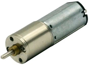
This guide follows widely‑accepted industrial sizing logic adapted to I.CH Motion planetary gearbox portfolio. It introduces a practical, risk‑oriented workflow to define application requirements, calculate target torque, apply proper safety service factors, differentiate mechanical and thermal performance limits, match gearbox designs against real‑world working conditions, and verify mounting‑related constraints. This structured workflow helps engineers avoid common specification mistakes caused by ignoring shock loads, frequent direction changes, long‑hour continuous running and inertia‑driven torque spikes, so as to achieve reliable service life with safe operating margins.
1. Define Full Application Operating Baseline
All torque‑related selection work starts with clear documentation of drive source, driven load, working cycle and operating environment. Many engineers only refer to motor nameplate data while ignoring real‑world dynamic load conditions, which is one of the most frequent root causes for improper gearbox selection.
1.1 Driver & Driven Equipment Profiles
Collect key information of your driving motor: motor type, working voltage, input speed, peak performance characteristics and control mode. For driven machinery, confirm steady‑state working demand, acceleration‑related load fluctuation, shaft side load conditions and system rotational inertia. Equipment with large inertia will generate obvious torque spikes during startup, and such transient loads must be taken into consideration in selection instead of being treated as negligible disturbances.
I.CH Motion provides two main categories of planetary gearbox solutions: compact miniature planetary units for precision light‑to‑medium torque scenarios, and heavy‑duty flange‑style planetary reducers for high‑torque industrial applications. Each product family is optimized for distinct application scenarios.
1.2 Duty Cycle Loading Profile
Working cycle directly influences fatigue wear on gear sets and bearings, and determines the safety margin required for torque selection:
- Intermittent single‑shift operation with stable load
- Long‑hour daily running or moderate shock load: increase safety margin appropriately
- Non‑stop 24‑hour operation with frequent start‑stop actions: adopt higher safety multiplier
- Frequent bidirectional rotation and heavy shock impact: apply minimum extra safety allowance
Below are general reference values for typical high‑torque scenarios: packaging automation, intelligent mobility equipment, portable precision tools, winch and slewing actuators all require different service factor ranges based on their load characteristics.
1.3 Environmental Constraints
Ambient temperature, dust, moisture and cleaning requirements will affect the sustainable working performance of high‑torque planetary reducers. Standard lubricants will degrade under long‑time high‑temperature conditions and weaken continuous working capacity. Outdoor, high‑temperature or washdown‑required working environments need matched lubricant grades and sealing solutions to maintain stable long‑term performance. Harsh working scenarios should select gearboxes with corresponding protection levels to avoid performance decline caused by contamination.
2. Calculate Base Output Torque & Reduction Ratio
After sorting out complete application conditions, work out theoretical output torque and reduction ratio before adding safety margins.
Reduction ratio equals motor input speed divided by target output speed. Planetary gearboxes adopt standardized multi‑stage design for different ratio ranges. If your calculated theoretical ratio cannot match standard options, pick the nearest available standard ratio and recheck working performance before adding safety factors.
Pay attention to efficiency loss brought by multi‑stage transmission. Each gear stage creates minor power loss, and accumulated efficiency drop should be considered to get realistic usable output torque and prevent under‑selection.
3. Apply Industry‑Standard Service Factor for Safe Torque Margins
Service factor is the core guarantee for safe high‑torque gearbox selection. It works as a multiplier applied to baseline load torque to offset fatigue risk, shock impact and cyclic load conditions not reflected by catalog nominal ratings.
Design Torque = Measured Maximum Load Torque × Service Factor
Nominal catalog parameters are tested under stable ideal working conditions. Most practical industrial high‑torque working scenarios require service factors higher than baseline values to lower premature‑failure risks.
Two sets of performance indicators must both be evaluated during selection:
- Mechanical Torque Rating: Maximum torque that gear assembly and bearing structure can sustain under long‑term operation within expected service life. It acts as the primary selection reference for most room‑temperature intermittent‑use machinery.
- Thermal Torque Rating: Maximum sustainable torque without excessive temperature rise. For multi‑stage gearboxes, compact enclosed housings and non‑stop running conditions, thermal performance often becomes the bottleneck even if mechanical performance meets theoretical demands. When thermal capacity cannot satisfy working requirements, optimize cooling conditions or choose a properly larger gearbox frame size.
For high‑inertia applications with strong acceleration impact, peak torque inspection is indispensable. Instant impact load shall not exceed reasonable overload threshold of gearboxes. Soft‑start control functions can effectively cut down peak torque demand and help realize cost‑effective gearbox selection without sacrificing safety.
4. Match Planetary Gearbox Construction to High‑Torque Demands
I.CH Motion planetary gearbox product lines adopt differentiated structural designs, and each design carries distinct performance trade‑offs for high‑torque working requirements.
Miniature Micro Planetary Series
Compact coaxial cylindrical structures built for space‑limited precision equipment. Standard bearing configurations fit intermittent light‑shock working conditions, while upgraded bearing options improve shaft load resistance and extend service life. Single‑stage and two‑stage structures realize torque amplification within limited installation space, which is widely adopted in portable devices and compact mobility hardware.
High‑Precision Flange Planetary Reducers
Square flange mounting design together with reinforced bearing assembly and high‑strength gear components deliver reliable high‑torque performance for robotics, automated production lines and general industrial automation. Optimized housing structure copes with elevated shaft loads, and low‑backlash gearing maintains stable output performance under frequent forward‑reverse operations. These units feature better heat dissipation capacity and higher shock‑resistant overload capability compared with miniature planetary models.

Thanks to multi‑planet load‑sharing principle, planetary gearboxes spread load evenly across multiple gear teeth. Compared with worm‑gear and parallel‑shaft reducers, they can realize high‑torque transmission with more compact volume and lighter weight, lowering mounting stress for the whole mechanical system.
5. Validate Mounting, Shaft Loads & Special Application Specifications
Even if torque calculation matches product specifications, installation‑related factors may weaken actual usable performance of gearboxes, so final‑step verification cannot be omitted.
- Mounting Orientation: Horizontal, vertical and wall‑mounted installation modes change lubricant distribution and bearing stress status. Improper installation posture may lead to poor lubrication and reduced service performance.
- Shaft Overhang & Axial Thrust: Pulley, sprocket and tooling fitted on output shaft bring extra radial and axial loads. Excessive side load will accelerate bearing wear even when working torque stays within nominal scope. Please refer to product guidelines for allowable shaft load limits.
- Industry‑Specific Special Requirements: Food‑related washdown environments need food‑grade lubricants; special‑condition automation scenarios require matched sealing and structural treatments to sustain stable long‑term operation.
6. Industry Application Torque Sizing Case Studies
Case 1: Automated Packaging Conveyor Drive
Equipment runs long hours every day with occasional product‑jam shock and frequent start‑stop actions. After determining proper service factor, we get target design torque and select I.CH Motion flange‑type planetary gearbox, meanwhile verify thermal performance to avoid overheating risk during long‑time operation.
Case 2: Portable Precision Power‑Tool Drive
Intermittent operation, frequent rotation reversal and obvious transient torque shock. Higher service factor is required. Choose miniature planetary gearbox with reinforced bearing configuration to withstand periodic shock load and prevent permanent gear damage.
Case 3: Consumer‑Grade Smart Mobility Device
Stable low‑shock intermittent working condition, moderate service factor. Miniature planetary gearbox meets torque demand under strict space‑limitation requirements for consumer equipment.
I.CH Motion full‑range planetary gearboxes comply with mainstream global quality standards. Customizable gear ratios, shaft forms, protection grades and lubrication schemes support diversified high‑torque application demands. Communicate with our application engineers with your complete working‑condition information to avoid waste caused by over‑specification and failure risks brought by under‑specification, and obtain planetary gearbox solutions delivering steady and safe torque output throughout its whole service cycle.