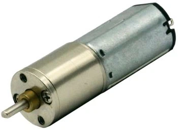
Environmental analytical automation equipment, such as automatic water-sampling monitors deployed for wastewater and surface-water surveillance, heavily depends on compact DC geared actuators to implement fluid handling workflows. OEM mechanical engineering teams navigate a complicated transition path: starting from technical inquiry, drawing iteration, prototype sample evaluation, all the way to stable serial production with thousands-of-units annual demand. Many motion-project delays originate from misaligned expectations between equipment OEM and motor manufacturer around sample-testing objectives, drawing-confirmation procedure, and how application-specific load influences motor performance. This article illustrates real-world project-management insights for compact planetary DC gear-motor projects targeting analytical instrument silicone-tube-compression actuation scenarios.

A successful gear-motor project starts from complete requirement documentation. When drafting your inquiry specification document, separate non-negotiable hard constraints and negotiable optimization space. Hard constraints cannot be compromised, otherwise the motor physically cannot fit or survive inside your equipment enclosure. These constraints contain operating DC voltage, maximum motor outer-diameter dimension, output-shaft size with D-flat cutting feature, continuous load-torque requirement and maximum acceptable no-load current. On the other hand, exact gear-reduction ratio can offer a reasonable window, for example 300-500:1, instead of demanding one single fixed ratio number at early inquiry phase.
Manufacturing of multi-stage planetary gearboxes relies on stacking discrete standard gear stages. Every gear stage multiplies reduction ratio according to pre-defined tooth-count combinations. Not every arbitrary integer reduction-ratio value can be physically manufactured. For instance, if customer points to two candidate target ratios, the motor-maker needs to check internal gear-stage library and select the closest achievable solution, then issue 2D mechanical drawing for customer cross-verification. Skipping drawing-review step and directly ordering samples will generate high risk of mechanical-interface mismatch upon sample arrival.
A frequently-observed communication pattern in real industrial inquiries unfolds in the following sequence:
- OEM releases motor specification sheet, states annual mass-production forecast and desired sample quantity for lab test.
- Motor supplier requests supplementary application context: photos, mechanical sketches or short demonstration video of existing equipment.
- OEM clarifies core application logic: motor squeezes silicone tube; rotational speed is secondary; top priority is preventing gear reverse rotation once power is switched off.
- Motor engineering department selects feasible gear-ratio variant, generates mechanical drawing, prepares quotation covering sample lot and large-volume yearly order.
- OEM reviews drawing and quotation document, gives formal confirmation.
- Supplier arranges sample fabrication, ships prototype units for customer bench-top testing.
- OEM executes functional test under real silicone-tube load, validates torque output and power-off position retention, then approves transition to mass-production phase.
This communication sequence highlights a critical insight: datasheet numbers alone cannot fully replace application-context exchange. Motor engineers need to understand how your mechanism actually works, how silicone tube spring-back force applies static reverse torque onto output shaft, and how the motor gets mounted inside instrument housing. Without that contextual background, even parameter-perfect motor may fail under real-world cyclic load.
Sample ordering deserves careful planning. For this class of analytical instrument actuation projects, practical sample quantity usually sits in the range of three to five prototype pieces. Why not just one sample unit? Multiple physical samples help engineers observe unit-to-unit mechanical variation within manufacturing tolerances. If you only test one single motor sample that happens to perform exceptionally well by random tolerance stacking, you will gain over-optimistic evaluation result which cannot represent future mass-production batch consistency. Testing several prototype motors exposes potential variance risk before committing to large-volume procurement.
Table-2 lists recommended test items you should run on received prototype gear-motor samples for silicone-tube squeezing actuation:
|
Test Item |
Test Objective |
|
Dimensional check against supplier drawing |
Verify shaft dimension, outer diameter and mounting feature |
|
No-load current measurement |
Confirm no-load current stays within upper-limit specification |
|
Load torque test with actual silicone-tube assembly |
Validate motor can reliably compress tubing under working condition |
|
Power-off back-driving / position-holding test |
Observe if output shaft drifts backward caused by silicone tube rebound |
|
Cyclic endurance preliminary test |
Run repeated squeeze-release cycles to detect early-wear anomaly |
Among these test items, power-off anti-back-driving assessment ranks high priority. Engineers must understand that high-ratio planetary gearbox is not equal to genuine self-locking. Worm-gear transmission achieves inherent self-locking via thread-friction geometry; planetary gear systems build resistance to reverse rotation by accumulated multi-stage friction losses. Holding performance will shift according to actual load magnitude, lubrication status and component wear over lifecycle. Physical testing with your real silicone-tube hardware is mandatory.
Commercial quotation handling also needs dual-perspective thinking: prototype sample pricing versus mass-production pricing. Sample batches incur non-recurring setup cost for drawing adjustment, custom-shaft machining and small-batch gear-box assembly work. Hence per-piece sample price will be considerably higher than serial-production unit price for thousands-quantity orders. Ask your motor vendor to deliver quotation covering both sample lot and forecast annual order volume in one package, supporting your full-lifecycle cost estimation for instrument product.
Drawing confirmation is a formal gate before sample manufacturing starts. Verbal confirmation via instant-message tool is insufficient. OEM team should provide written confirmation email explicitly approving mechanical drawing and quotation terms. This step eliminates ambiguous understanding on gear-ratio, shaft geometry, gear-material (all-metal versus plastic gears) and commercial terms. If drawing details get modified later without formal written alignment, hardware mismatch problems may emerge.
After samples successfully pass lab testing, project can advance toward mass-production preparation. At this stage, both parties should re-confirm key technical baseline: gear-material definition, finalized gear-ratio, shaft D-flat dimension, acceptance criteria derived from sample-test results.
To conclude, the prototype-to-production journey for environmental-instrument planetary DC gear-motor emphasizes structured requirement documentation, application-context exchange, formal drawing-approval workflow, multi-unit-sample testing and separating sample-cost versus mass-production-cost. Avoid treating gear-motor procurement as pure datasheet-parameter matching work. Real silicone-tube mechanical load creates unique constraints that only practical bench-top evaluation can expose. Following structured project-gate steps significantly lowers redesign risk for your automated environmental-monitoring analytical equipment.